Mount and power
With the site set up in the app, fit the device: pick a good spot, fix it to the wall on two screws, and give it power. The drawings below are mechanical guidance. All dimensions are in millimetres.
Placement
Good placement is what makes the readings trustworthy. The aim is air that represents the whole room, not a local hot spot by a window, a door or a heater.
Where in the room
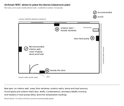
Mount on an interior wall: a wall with no outdoor-facing side. Keep clear of windows, exterior walls, doorways and heat sources.
Mounting height
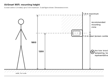
Fix the device so the screen centre is about 1.2 m above the floor. Anywhere up to 1.8 m is fine. Lower than 1.2 m invites knocks and tampering and reads less representative air.
Sun and heat
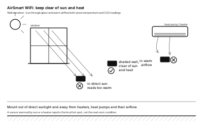
Keep the device out of direct sunlight and away from heaters, heat pumps and their airflow. A sensor warmed by sun or a heater reports its own hot spot, not the room.
Clearance for airflow
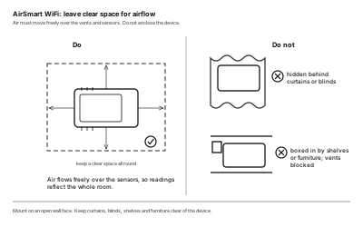
Air has to move freely over the vents and sensors. Do not enclose the device behind curtains or blinds, or box it in with shelves or furniture.
Mounting
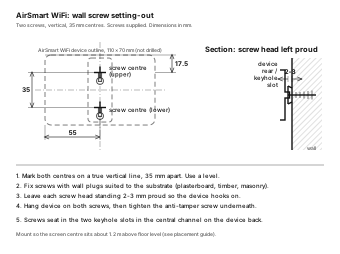
The device hangs on two screws set in a vertical line, 35 mm apart, which seat in the two keyhole slots in the central channel on the back. Leave each head a little proud, hang the device, then lock it with the anti-tamper screw underneath.
Power and cabling
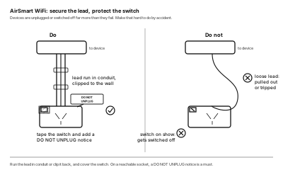
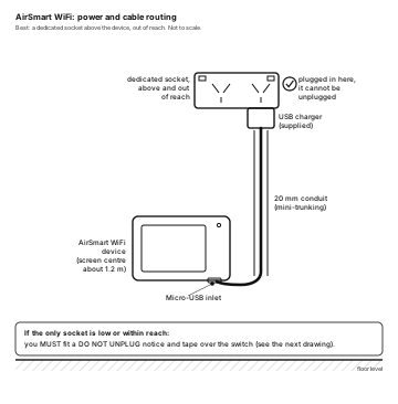
The device runs on the supplied Micro-USB charger, which plugs into a mains socket. Best is a dedicated socket above the device, out of reach, so it cannot be unplugged. Run the lead down to the device inside 20 mm conduit, with soft bends.
Keep it powered
Devices get unplugged or switched off far more often than they fail. Secure the lead so it cannot be pulled, and cover the wall switch.
If the device has to run from a socket that is low or within reach, you must fit a DO NOT UNPLUG notice and tape over the switch. This is a required step in the install, not a nice-to-have.